ST��˾��RHRPMPOL01�dž��ཱུ����Ƭ�_�P������,�����˸߾��ȃȲ�����늉�������ͬ���D�Q�Ĺ���MOSFET.��������SOI���g,���������V�iЧ�������õ�����.RHRPMPOL01��ݔ��늉�3.0V��12V�D�Q�� 8V��0.85xVINݔ��늉�.�OӋ���ڿ��g���õ�FPGA,DSP,MCU��ASIC���Դ.�����Ŀ������ǻ��ڷ�ֵ����ܘ�,�Ķ����C�˿��ؓ�d˲�B푑��ͺܷ������_�P�l��.Ƕ��ķe�����a������ݔ��늉����y�������DC늉��`��.���Ϲ����������]�iݔ���^�����o,�^�����o���Ԅӻ֏͵ğᱣ�o.ݔ��������_7A,�����ض�-55 C �� +125 C,�ɾ��_�P�l�ʏ�100kHz��1MHz.RHRPMPOL01���x�ӄ�����100 krad,�o�������V�iЧ�����_70 MeV/mg/cm2 (@ VCC up to 7 V),SEU-SEFI���Ը��_VCC 7V,�o�|��.��Ҫ���ڿ��g���õ��cؓ�d������,FPGA,DSP,CPU��ASIC�Դ�Լ��͉����ܶȷֲ��Դϵ�y.���Ľ�B��RHRPMPOL01��Ҫ����,��D,���͑����·�D����
����Ԫ����.�Լ��u����EVAL-RHRPMPOL01��Ҫ����,�·�D,������κ�PCB�OӋ�D.
The RHRPMPOL01 is a single phase, step-down monolithic switching regulator with
high precision internal voltage reference and integrated power MOSFETs forsynchronous conversion. The device has been developed using SOI technology thatoffers good performance against SEL effect.
The regulator converts 3.0 V to 12 V input voltage to 0.8 V to (0.85xVIN) outputvoltage. It has been designed to supply FPGA, DSP, MCU and ASICS in general forspace applications.
The controller is based on peak current mode architecture, which ensures a fast load
transient response and very stable switching frequency. An embedded integratorcompensates the DC voltage error due to the output voltage ripple. The faultmanagement consists of not-latched output overvoltage protection, overcurrentprotection and auto recovery thermal protection.
RHRPMPOL01��Ҫ����:
• 3.0 V to 12 V input operating voltage range (target radiation performanceguaranteed at VCC up to 7 V)
• 0.8 V to (0.85xVIN) output voltage range
• Up to 7 A output current
• Wide operating temperature range -55 C to +125 C
• Single supply
• Integrated N-channel MOSFETs for synchronous step-down conversion
• Integrated BOOT diode
• Programmable switching frequency: from 100 kHz to 1 MHz
• Fast load transient response and simple loop compensation based on peakcurrent mode control loop
• Easy synchronization with 180 out-of-phase (up to 2 ICs) management
• Current sharing configuration for higher load requirements
• Lossless current sensing based on sense-FET
• Not-latched output overvoltage protection
• Adjustable output overcurrent protection
• Input undervoltage protection
• Latched overtemperature protection
• Power Good output pin
• Programmable soft-start with increased current capability
• Hermetic ceramic package qualified for space applications FLAT-28
• Target radiation performance:
�C Total ionizing dose: 100 krad
�C Tested ELDRS-free
�C SEL-free up to 70 MeV/mg/cm2 (@ VCC up to 7 V)
�C SEU-SEFI characterized up to VCC 7 V
�C Proton free
�C No performance degradation due to SET
�C QMLV qualification ongoing
RHRPMPOL01����:
• Point of load regulation for space application
• FPGA, DSP, CPU and ASICS supply
• Low voltage, high density distributed power systems
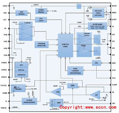
�D1.RHRPMPOL01��D
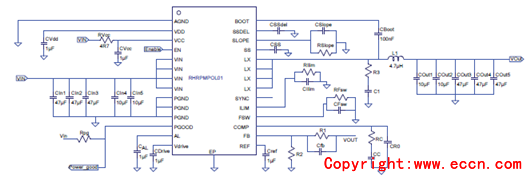
�D2.RHRPMPOL01���͑����·�D
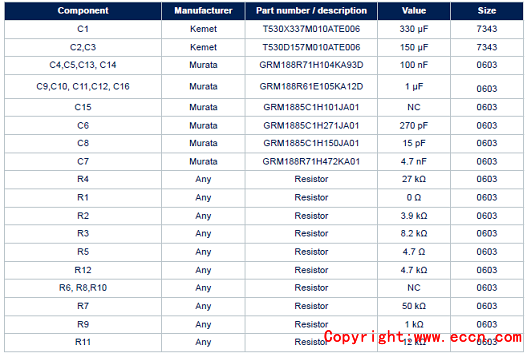
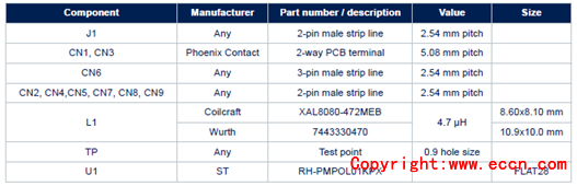
�D2�����·�D�е�����Ԫ����:
�u����EVAL-RHRPMPOL01
EVAL-RHRPMPOL01 evaluation board of radiation hardened 7 A monolithicsynchronous switching regulatorThis user manual provides an overview of the use of the EVAL-RHRPMPOL01 evaluation board. It has been developed andoptimized for a typical application of the RHRPMPOL01 device, a single phase, step-down monolithic switching regulator withhigh precision internal voltage reference and integrated power MOSFETs for synchronous conversion. The regulatorRHRPMPOL01 converts 3 V - 12 V input voltage to 0.8 V - (0.85xVIN) output voltage. The controller is based on a peak current
mode architecture, which ensures a fast load transient response and very stable switching frequency. An embedded integratorcompensates the DC voltage error due to the output voltage ripple.
�u����EVAL-RHRPMPOL01��Ҫ����:
• Input operating voltage: 5.0 V
• Output voltage: 1.2 V
• Output current: up to 5 A
• Enable input voltage: 2.5 V
• Switching frequency: 500 kHz
• Output overcurrent protection: 10 A
• Easy synchronization with 180 out-of-phase (up to 2 ICs) management
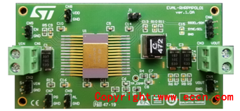
�D3.�u����EVAL-RHRPMPOL01���ΈD
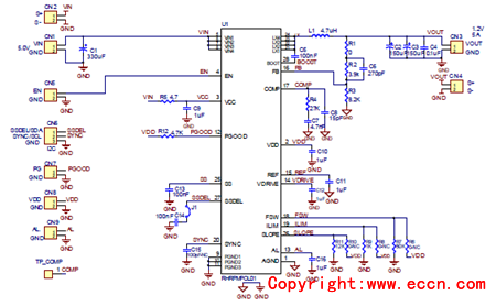
�D4.�u����EVAL-RHRPMPOL01�·�D
�u����EVAL-RHRPMPOL01�������:
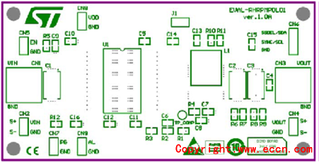
�D5.�u����EVAL-RHRPMPOL01 PCB�OӋ�D:플��b��

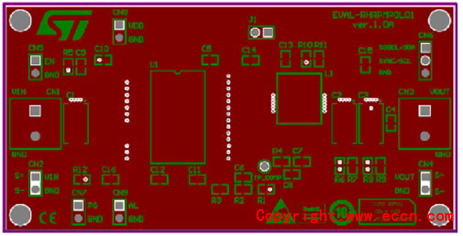
�D6.�u����EVAL-RHRPMPOL01 PCB�OӋ�D:플�
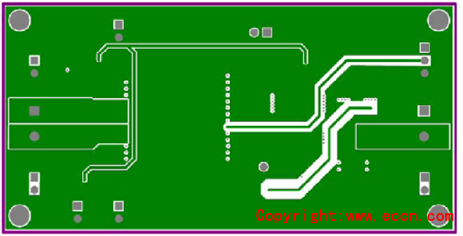
�D7.�u����EVAL-RHRPMPOL01 PCB�OӋ�D:���g��1
�D8.�u����EVAL-RHRPMPOL01 PCB�OӋ�D:���g��2

�D9.�u����EVAL-RHRPMPOL01 PCB�OӋ�D:�� |